Terracotta Baguette Fixing Methods: Selection and Coordination
Compare terracotta baguette fixing approaches by orientation, span, support, restraint, movement, access and the engineering evidence each project needs.
Historical archive: product availability, standards and event information may have changed. Contact LOPO for current specifications.Terracotta baguette fixing methods should be selected from the element’s orientation, profile, span, loads, support geometry and replacement strategy. A screw visible in a photograph does not explain the complete load path or prove that the same arrangement suits another facade.
This guide helps architects, facade engineers, contractors and suppliers coordinate a fixing concept. The appointed engineer must determine design actions, capacities, connections and acceptance criteria under the project’s regulations. LOPO can provide available product and component information, but it does not replace project engineering.
Define the Baguette’s Role Before Selecting Fixings
State whether the baguette is a decorative screen, shading element, privacy layer, louver or part of another facade composition. Record horizontal, vertical or inclined orientation; profile and finish; proposed length; spacing; support locations; distance from the building; public accessibility; and interfaces with glazing, cladding, structure and maintenance equipment.
The LOPO terracotta baguette overview shows current product families and profiles. Final feasibility depends on the selected item and project support arrangement rather than the category name alone.
| Selection question | Why it affects the fixing concept | Evidence to coordinate |
|---|---|---|
| What is the orientation? | Gravity, wind response, drainage, slip and erection sequence change | Elevations, sections and orientation schedule |
| Where can supports occur? | End, intermediate or framed supports create different spans and local actions | Structural grid, bracket zones and access study |
| How is movement managed? | Over-restraint can introduce unintended stress; insufficient restraint can allow displacement | Movement analysis and fixed-or-sliding connection logic |
| What are the consequences of damage? | Height, public areas and replacement access affect the risk-control strategy | Project risk assessment and maintenance plan |
| Which components touch the clay? | Bearing, isolation, fit and local geometry influence the interface | Product drawings, samples and component data |
| How will a unit be replaced? | Fastener access and installation order can lock adjacent elements in place | Replacement sequence and mock-up record |
Compare Fixing Concepts, Not Marketing Names
End-Supported Horizontal Baguettes
A horizontal unit may be supported near its ends by pins, rods, carriers, brackets or another proprietary arrangement. The engineer should check the baguette between supports, the local clay interface, rotation, lateral restraint, movement and the supporting frame. Do not assume that end support is suitable for every length or profile.
Vertically Oriented Baguettes
Vertical elements require a defined gravity support and restraint strategy. Clarify which connection carries permanent action, which controls out-of-plane response, and how differential movement is accommodated. Installation order and access to upper and lower connections should be shown.
Intermediate Supports or Multi-Point Restraint
Additional supports may be considered where geometry, actions or risk assessment require them. Their positions change the baguette’s structural behavior and tolerance demands. Each support should have a stated function; adding an uncoordinated clip can create unwanted restraint instead of useful capacity.
Prefabricated Frames or Modular Screens
Baguettes may be assembled into a secondary frame or cassette before installation. This can shift site work into controlled fabrication, but introduces frame connections, transport, lifting and module-to-building interfaces. Review the complete module rather than treating the clay pieces in isolation.
Trace Loads Through Every Interface
Document the path from the baguette to pins or clips, brackets, rails or frames, anchors and the primary structure. The engineer should establish relevant wind, permanent, seismic, impact, thermal, maintenance and other project actions, along with combinations and facade zones required by local rules.
Check product and component properties against the proposed configuration. The LOPO back fixing component overview provides examples, while the ventilated facade engineering guide explains the calculation and evidence package. Typical components still require project verification.
Coordinate Fit, Movement and Durability
- Identify the exact profile, cavities, fixing holes or inserts and permitted contact zones.
- Define bearing materials, isolators, washers and interfaces without assuming interchangeability.
- Allow assessed building, frame and material movements while retaining the unit as designed.
- Coordinate drainage so water is not trapped at cavities, caps or horizontal ledges.
- Review dissimilar materials, coatings, exposure and accessible edges within the corrosion strategy.
- Show anti-rotation, anti-slide or secondary restraint only where engineered and supported by evidence.
- Protect openings and fixing zones from unapproved site cutting or drilling.
Prepare a Coordinated Submittal
Submit a basis of design, product schedule, component data, calculations, relevant reports, elevations, sections and enlarged fixing details. Drawings should identify support and restraint functions, fastener access, adjustment, movement, interfaces, installation sequence and replacement method. Mark different profiles and orientations with traceable codes.
Testing or assessment may be required when proprietary connections, brittle behavior, impact, unusual profiles or system interaction cannot be established by calculation alone. The responsible team should define the specimen, method and acceptance criteria, then compare the tested arrangement with the proposal.
Use Samples and Mock-Ups to Check Buildability
A physical assembly can reveal fit, bearing, alignment, joint rhythm, visual rotation, fastener access and replacement constraints. It does not replace structural verification. Record the approved components, tolerances and installation order so the benchmark can inform site inspections.
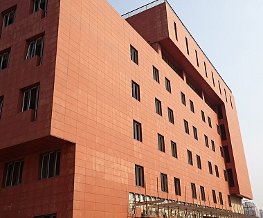
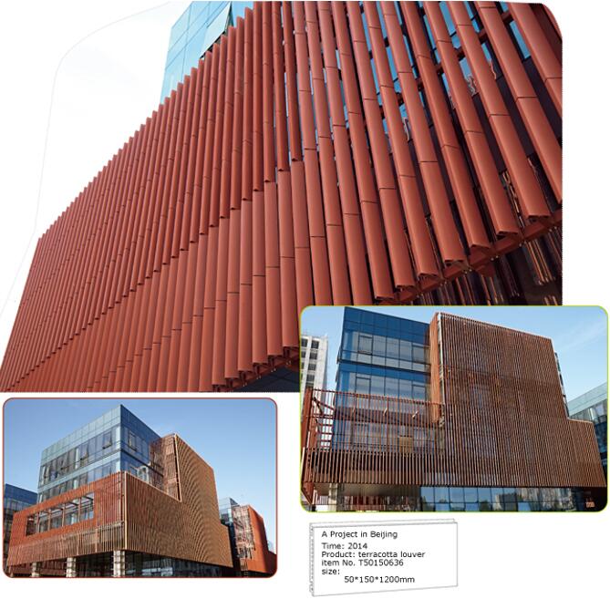
The historical photographs below remain useful as design context. They show a red baguette facade and an installation view, but not the concealed system or engineering basis.


Inspect Installation Against the Approved System
Survey supports and set-out before fixing. Verify component identities, anchors, brackets, frame alignment, isolators, baguette orientation, seating, restraints and connection completion. Quarantine cracked units or damage near fixing zones. Record concealed work and close nonconformances before the next layer removes access.
The product listing at LOPO terracotta baguette items can help identify candidate codes, but current drawings, samples and project documents should govern procurement and installation.
Frequently Asked Questions
Is there one standard fixing method for every terracotta baguette?
No. The fixing concept depends on product geometry, orientation, span, actions, supports, access, evidence and local requirements.
Can long baguettes be supported only at their ends?
Do not assume so. The appointed engineer should verify the exact profile, proposed length, support conditions and actions using applicable product data and evidence.
Are horizontal and vertical baguette fixings interchangeable?
No. Gravity support, restraint, movement, drainage, installation and replacement differ. Each orientation needs a coordinated detail and review.
Does a mock-up prove structural capacity?
Not unless it forms part of a defined test or assessment. A visual mock-up primarily checks appearance, fit and buildability; structural evidence must follow the approved engineering route.
Request Information for a Defined Fixing Concept
Send the baguette profile, orientation, proposed length, spacing, support concept, elevations, sections and project location through the LOPO project enquiry page. The project team remains responsible for design, testing decisions, installation and regulatory compliance.