Terracotta Panel Installation: Coordination and Inspection
Plan terracotta panel installation with coordinated drawings, substrate checks, approved materials, hold points, inspections and documented handover.
Historical archive: product availability, standards and event information may have changed. Contact LOPO for current specifications.A terracotta panel installation should proceed from approved project documents, not from a generic online sequence. Panel type, subframe, anchors, joints, cavity, fire strategy and interfaces vary by building. The appointed facade engineer, architect, contractor and relevant authorities must define the requirements for the actual project.
This terracotta panel installation checklist focuses on coordination, inspection and traceable records. It can support a site quality plan, but it does not replace engineered shop drawings, method statements, manufacturer instructions, testing, permits or competent supervision.
Confirm Responsibilities Before Site Work
Create a responsibility matrix before materials arrive. Identify who designs the support system, approves anchors and substrates, coordinates fire and weather barriers, releases samples, inspects concealed work, accepts deviations and signs the handover. Where more than one supplier provides panels, brackets, rails or anchors, assign responsibility for every interface.
The selected unit should be identified from the LOPO terracotta panel range or the approved project schedule. Product information is only one input; the installed assembly remains project-specific.
Use Hold Points, Not Assumptions
| Stage | Control point | Record before release |
|---|---|---|
| Design coordination | Panel module, joints, subframe, anchors, movement, interfaces and access are resolved | Approved drawings, calculations and document register |
| Material receipt | Panels and components match the approved codes, finishes and revisions | Delivery inspection, labels, photographs and nonconformance log |
| Substrate survey | Structure, embeds, edges and tolerances suit the approved fixing design | Survey report and disposition of deviations |
| First installed area | Set-out, brackets, rails, cavity layers, panels and joints are coordinated | Signed first-work or benchmark inspection |
| Concealed work | Anchors, brackets, rails, barriers and fire-related details are visible for review | Inspection checklist and dated photographs |
| Completion | Appearance, restraint, interfaces, cleaning and replacement access are reviewed | Completion record, as-built information and maintenance handover |
Review the Installation Package
- Approved elevations, sections, details, panel schedule and setting-out coordinates
- Structural calculations and specified design actions for the complete support path
- Anchor, bracket, rail, clip, restraint and isolation-component data
- Product drawings showing panel orientation, grooves or fixing interfaces
- Method statements for access, lifting, installation, temporary stability and replacement
- Inspection and test plan with hold points, acceptance criteria and responsible reviewers
- Coordinated fire, air, water, insulation, drainage and flashing details
- Approved samples, mock-up records and finish-variation criteria
Structural calculations and their supporting information are addressed separately in the ventilated facade engineering guide. Site personnel should have the released installation revision, not an earlier tender drawing.
Inspect Deliveries, Storage and Traceability
Compare crate labels and packing lists with the approved panel schedule. Check item codes, dimensions, finish references, orientation marks, quantities and visible transport damage. Photograph damaged packaging before moving it, quarantine suspect units and follow the agreed reporting process.
Store panels and components using the project method so faces, edges, fixing grooves and coatings are protected. Keep batches and installation zones traceable. Do not mix substituted clips, rails, anchors or isolation materials into the work without documented review and approval.
Survey the Substrate and Establish Set-Out
Verify the supporting structure against the coordinated drawings before drilling or fixing. Survey datum lines, slab edges, embeds, openings, corners and interfaces. Record out-of-tolerance conditions; do not force the subframe to absorb deviations unless the engineer has allowed and reviewed that adjustment.
Set out control lines that link facade joints to openings, floors, corners and adjacent materials. Recheck them as work progresses so small errors do not accumulate across an elevation. Confirm that rails and brackets remain within their permitted adjustment and that movement provisions are not locked.
Follow the Approved Assembly Sequence
- Release the substrate. Close survey and anchor-base issues before covering them.
- Install anchors, brackets and primary supports. Use the approved components, tools, torque or installation controls and inspection method.
- Coordinate cavity layers. Inspect membranes, insulation, flashings, drainage paths and fire-related details before they become concealed.
- Install rails, clips and restraints. Check alignment, isolation, connections and compatibility with panel grooves. The back fixing component overview shows typical component families, but project drawings govern.
- Place panels in the approved sequence. Protect edges, maintain designed joints and avoid unapproved cutting, drilling, packing or adhesive.
- Complete interfaces. Resolve corners, openings, parapets, bases and transitions exactly as coordinated. Review the terracotta facade corner options as design references, not automatic site details.
Archived Installation Sequence Images
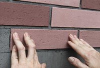
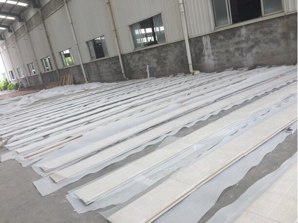
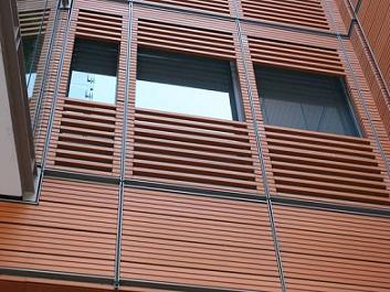
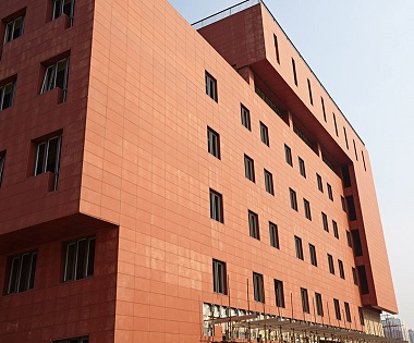
The photographs below are retained from the original 2015 article as an illustrative sequence. They do not define a universal fixing method. Profiles, anchors, brackets, fasteners, joint details, fire-stopping and tolerances must follow the approved project drawings, calculations, test evidence and installer method statement.


Inspect Work as It Becomes Concealed
Inspections should verify component identity, anchor location, embedment or engagement, rail alignment, connection completion, isolation between dissimilar materials, panel seating, restraints, joint geometry and cavity continuity. Acceptance criteria must come from the project documents and applicable regulations.
Use a benchmark area to align expectations among the architect, engineer, contractor and installer. Record its location and approved condition. For repetitive work, define inspection frequency and sampling in the quality plan rather than relying on informal visual checks.
Control Deviations and Repairs
Stop and record cracks, chips at fixing zones, misaligned rails, enlarged holes, missing restraints, damaged coatings or unapproved component changes. A site repair should have a documented method and acceptance route. Concealing a deviation behind the next panel makes later diagnosis harder.
Panels that do not seat naturally should not be forced into place. Investigate the product code, orientation, rail position, clip compatibility and accumulated tolerance. Refer structural or recurring problems to the appointed engineer and system designer.
Clean, Inspect and Hand Over
Protect the facade from mortar, metal swarf, sealant and runoff during construction. Test any cleaning method on the actual finish and adjacent materials, using manufacturer-approved guidance. Do not assume that pressure, chemicals or abrasive tools are suitable.
At completion, provide as-built drawings, product and batch records, inspection photographs, test results, approved deviations, cleaning information, replacement procedure and access requirements. The owner should receive a facade inspection and maintenance plan prepared for the building.
Frequently Asked Questions
Can this checklist replace the installer’s method statement?
No. It identifies coordination and inspection topics. The competent contractor must prepare a project-specific method aligned with approved engineering, product instructions, site conditions and regulations.
Who approves the terracotta panel fixing layout?
The responsible facade or structural engineer and project reviewers should approve it under the project’s responsibility structure. A product supplier’s typical detail is not automatic approval.
What should happen if the substrate is out of tolerance?
Record the survey result and obtain an approved disposition. Do not improvise bracket extensions, packing, slot changes or anchor relocation without engineering review.
Should every installed panel be checked?
The project quality plan should define inspections, sampling and hold points. Visible seating and damage require ongoing attention, while concealed anchors and supports need documented checks before closure.
Coordinate the Project-Specific Installation
Send product codes, elevations, sections, fixing concepts, quantities and project location through the LOPO project enquiry page. LOPO can clarify product and component information; engineering approval, site safety, installation and regulatory compliance remain with the appointed project parties.