
Terracotta Ventilated Facade Cavity Design Guide
Coordinate a terracotta ventilated facade cavity through drainage, airflow, membranes, openings, fire barriers, thermal bridges and moisture review.
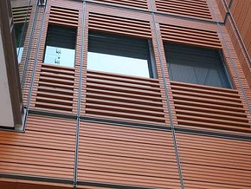
Historical archive: product availability, standards and event information may have changed. Contact LOPO for current specifications.Terracotta ventilated facade cavity design is a building-physics task, not a benefit created by the clay panel alone. The outer panels intercept weather and form the visible surface, while joints, the cavity, flashings, air- and water-control layers, insulation, brackets, openings, fire barriers, and drainage routes determine how the wall manages water, air, heat, and moisture. Every project must define these layers for its climate, exposure, substrate, geometry, regulations, and maintenance plan.
Define the Wall Strategy and Terminology
“Ventilated facade,” “drained and back-ventilated rainscreen,” and “open-joint cladding” can overlap, but terminology varies by market and standard. State the intended water-management strategy, air-barrier location, cavity function, ventilation route, compartmentation, and responsible designer. The rainscreen classification guide distinguishes common water-control concepts before a terracotta system is selected.
The visible panel is not normally the final air or water barrier. Use the terracotta facade panel overview to identify candidate products, then coordinate them with the backing wall and environmental strategy.
Set the Cavity Design Inputs
| Input | Question to resolve | Project output |
|---|---|---|
| Exposure | What wind-driven rain, wind pressure, temperature, humidity, salts, snow, or dust conditions apply? | Climate and elevation-zone design basis |
| Outer joints | Are joints open, baffled, overlapped, gasketed, or treated another way? | Joint geometry, tolerances, and water-entry assumptions |
| Cavity | What depth, continuity, obstructions, pressure paths, and drainage are intended? | Coordinated sections and cavity-zone drawings |
| Openings | Where does air enter or leave, and where must water discharge? | Top, base, sill, head, parapet, and interruption details |
| Backing wall | Which layers control air, water, vapour, and heat? | Continuous control-layer drawings and specifications |
| Fire strategy | Where are cavity barriers, fire stops, closures, and protected interfaces required? | Approved fire-stopping and compartmentation design |
Design Drainage Before Discussing Airflow
Water may pass through outer joints. The cavity should direct it to flashings and safe discharge points without relying on evaporation. Show positive laps, end dams where required, sills, heads, bases, parapets, penetrations, balcony interfaces, and transitions. Avoid ledges or blocked zones that can retain water against membranes, insulation, rails, or the substrate.
Drainage openings need adequate placement and a route to the exterior. Insect meshes, closures, sealants, mortar, insulation, rails, and cavity barriers must not unintentionally block them. Define how installers inspect concealed drainage before panels close the cavity.
Treat Ventilation as a Project Variable
Do not promise a universal “chimney effect,” cooling reduction, or dry cavity. Air movement depends on opening geometry, cavity depth and height, compartmentation, wind, stack pressure, temperature, obstructions, facade orientation, and surrounding buildings. Some zones may be well ventilated while others experience limited or reversing flow.
- Identify intended intake and exhaust or pressure-relief openings for each cavity zone.
- Check effective free area after meshes, closures, rails, brackets, and fire barriers are installed.
- Define whether the cavity is continuous, compartmented, pressure-moderated, or divided by elevation conditions.
- Use project-specific calculation, simulation, testing, or specialist judgement when airflow affects a performance claim.
- Keep energy modelling separate from product marketing; thermal outcomes depend on the complete envelope and building operation.
Coordinate Heat, Air, Vapour, and Moisture
Insulation continuity and thermal bridges through brackets, anchors, slab edges, windows, and parapets influence thermal performance. The air barrier should be continuous and connected to windows, doors, roofs, bases, and penetrations. Vapour control and condensation risk depend on climate, interior conditions, material properties, and layer order.
Where risk warrants it, use hygrothermal assessment with stated weather, occupancy, material, boundary, and construction-moisture assumptions. A ventilated cavity can support drying in some conditions, but it does not correct discontinuous membranes, trapped water, inappropriate vapour control, or wet materials concealed during construction.
Resolve Fire Barriers Without Defeating Water Control
Fire and moisture details must be designed together. Cavity barriers, fire stops, closures, membranes, insulation, rails, brackets, and outer panels should follow the project fire strategy and applicable approval route. Some devices may need to permit drainage or ventilation in normal service while performing another function under fire conditions; use only a documented project solution.
Show continuity at floor lines, compartment walls, openings, corners, parapets, bases, and interfaces with other facade types. Product descriptions do not approve the complete wall.
Detail Interfaces and Construction Sequence
- Freeze the control-layer locations, cavity zones, openings, flashings, and fire strategy.
- Coordinate brackets and anchors without creating unresolved penetrations or thermal bridges.
- Survey the substrate and repair air- or water-barrier defects before concealment.
- Inspect insulation, membranes, flashings, fire barriers, meshes, and drainage paths at defined hold points.
- Install rails and panels while maintaining specified cavity clearances and joint geometry.
- Record concealed work, approved deviations, drainage checks, repairs, and as-built access information.
For full panel, fixing, grid, load-path, and interface coordination, use the separate terracotta panel rainscreen system guide. Structural calculations and anchor submissions are covered by the ventilated facade structural engineering guide.
Verify the Environmental Strategy
Review large-scale details and a representative mock-up before production. The verification plan may include visual inspection, controlled water testing, air-leakage testing of the backing wall, drainage demonstrations, interface opening-up, or other project methods. Name the specimen, condition, acceptance criteria, responsible party, and limits of each check.
Plan ongoing inspection of joints, panels, flashings, discharge points, sealants where used, accessible cavity zones, and interfaces. Access and replacement should not depend on dismantling an undefined portion of the elevation.
Frequently Asked Questions
Does a ventilated cavity make the facade waterproof?
No. Water management relies on outer deflection, drainage, flashings, control-layer continuity, interfaces, and safe discharge. Ventilation is only one part of the strategy.
Is more cavity airflow always better?
No. Required airflow and compartmentation depend on the wall strategy, exposure, fire design, geometry, and local guidance. Uncontrolled openings can conflict with other requirements.
Does the terracotta panel provide insulation?
The panel is the outer cladding. Whole-wall thermal performance depends on insulation, air tightness, thermal bridges, backing construction, openings, and project modelling.
Who designs the cavity and membranes?
Responsibilities should be assigned in the contract. The architect, facade consultant, building-physics specialist, fire consultant, structural engineer, manufacturers, and installer may each provide coordinated inputs.
Request a Cavity Coordination Review
Send the location, elevations, exposure, panel and joint concept, cavity zones, backing-wall build-up, membranes, insulation, fire strategy, openings, interfaces, standards, mock-up plan, programme, and destination through the LOPO project enquiry page. LOPO can review current panel and fixing feasibility; the project team retains responsibility for the environmental design and regulatory approval.


