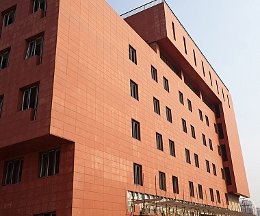
Terracotta Panel Rainscreen Systems: Design Coordination Guide
Understand how a terracotta panel rainscreen system coordinates panels, joints, cavity, rails, brackets, fixings, interfaces, testing and maintenance.
Historical archive: product availability, standards and event information may have changed. Contact LOPO for current specifications.A terracotta panel rainscreen system combines fired-clay cladding units with clips, rails, brackets, anchors, joints and the supporting wall. The panel is only the visible outer layer. Weather control, insulation, structural support, fire safety and interfaces depend on the coordinated assembly.
This guide outlines the decisions that architects, facade consultants, engineers, manufacturers and installers should resolve together. It focuses on system coordination rather than promising one universal detail. Project loads, codes, substrates and exposure conditions must be verified for the actual building.
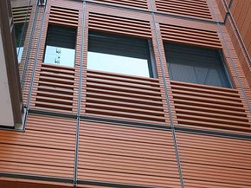
Core parts of a terracotta panel rainscreen system
| System layer | Primary role | Information to coordinate |
|---|---|---|
| Terracotta panel | Visible outer cladding and architectural surface | Profile, dimensions, orientation, tolerances, finish and edge conditions |
| Clips and rails | Retain panels and transfer actions to brackets | Engagement, spacing, anti-rattle measures, movement and replacement |
| Brackets and anchors | Connect the rail system to the backing structure | Substrate, load path, stand-off, adjustment and corrosion environment |
| Ventilated cavity | Provides drainage, ventilation and separation behind panels | Depth, continuity, openings, obstructions and compartmentation |
| Backing wall layers | Control air, water and heat as designed | Membranes, insulation, thermal bridges, penetrations and continuity |
| Interfaces | Complete the wall at edges and adjacent systems | Windows, doors, corners, parapets, base, roof and material transitions |
Establish the load path
The design team should identify how wind, self-weight, impact and other relevant actions pass from each panel through clips, rails, brackets and anchors to a suitable structure. Rail direction and support spacing cannot be selected from appearance alone. Panel orientation, profile, span, edge distance and local wind zones may affect the arrangement.
Project-specific calculations should be prepared or reviewed by qualified facade and structural professionals. Substrate capacity, anchor selection, bracket adjustment and movement need particular attention. Test reports are useful only when their products, configurations and methods are relevant to the proposed assembly.
Coordinate the panel grid with the support grid
Elevation modules should align with realistic panel sizes, joints and support locations. Create a coded schedule for typical panels, corners, returns and special pieces. Show the relationship between the visible joint grid and the hidden rail layout at windows, parapets, soffits and changes of plane.
Joints must accommodate manufacturing and installation tolerances as well as expected movement. Unplanned hard contact between ceramic units can cause damage. Details should also allow practical installation and, where required, removal of an individual panel without dismantling a large wall area.

Design drainage and ventilation paths
Open or baffled joints in a rainscreen are not the building’s final water barrier. Water that passes the outer layer should be managed by the cavity, flashings, membranes and drainage openings. Details need to direct water out at the base, above openings and at other interruptions.
Ventilation paths should remain continuous where the design requires them, while fire-stopping and cavity barriers must follow the project fire strategy. Insect screens, closures and flashings should not unintentionally block drainage. The base and top of each zone require deliberate details rather than a generic note.
Resolve thermal, fire and acoustic responsibilities
Thermal performance comes from the complete wall, including insulation continuity, air tightness and control of thermal bridges through brackets and fasteners. The panel itself should not be described as the insulation layer. Hygrothermal review may be needed for climate- and wall-specific moisture behavior.
Fire performance also belongs to the assembly and applicable regulatory route. Confirm the reaction-to-fire information for relevant products, combustibility and protection of other components, cavity barriers, fire-stopping around openings and any required system assessment. Acoustic performance likewise depends on multiple wall layers and should be supported by relevant testing or analysis.
Detail every interface
Many facade problems begin where typical wall zones meet other construction. Prepare large-scale details for inside and outside corners, window heads, sills and jambs, parapets, bases, soffits, roof transitions, balconies, penetrations and interfaces with glass, metal, stone or masonry.
Each detail should show drainage, membrane continuity, insulation, brackets, rails, clips, joint widths, sealants where used and installation access. Avoid relying on the terracotta panel to conceal an unresolved transition.
Plan samples, mock-ups and submittals
- Approved panel profile, dimensions, finish and representative color range
- Panel schedule and coordinated shop drawings
- Relevant product test reports with methods and specimen details
- System calculations and anchor information for the project conditions
- Samples of clips, rails, brackets, fasteners and visible accessories
- Mock-up scope, acceptance criteria and any performance testing
- Installation, inspection, cleaning and replacement instructions
Use the technical data verification guide to distinguish product evidence from complete-system evidence.
Installation and quality-control sequence
- Survey the substrate and confirm approved anchor locations and tolerances.
- Install brackets and rails to controlled lines and levels.
- Inspect membrane, insulation, flashings and cavity components before they are concealed.
- Install panels with the specified clips, engagement and joint spacing.
- Check alignment, damage, movement clearances and interface details by facade zone.
- Record replacements, spare units and final access requirements.
Site teams should not force out-of-tolerance panels or improvise clip details. Deviations should be recorded and resolved through the project’s technical review process.
Frequently asked questions
Is a terracotta rainscreen the same as a sealed curtain wall?
No. Terminology varies, but a rainscreen normally manages water through an outer cladding layer, a drained cavity and a separate air- and water-control layer. The project specification should define the intended wall build-up.
Who designs the rails, brackets and anchors?
Responsibilities must be stated in the contract documents. Qualified facade and structural professionals should verify loads, substrate, supports, anchors and interfaces using relevant manufacturer information.
Can one rail layout be used across the whole elevation?
Not necessarily. Panel orientation, geometry, wind zones, openings, corners, soffits and substrate conditions may require different support arrangements.
Does the cavity need maintenance access?
The design should allow inspection and replacement where reasonably required. Access needs depend on the building, zone, panel system and maintenance strategy.
From application idea to coordinated system
First identify where terracotta will be used with the guide to terracotta panel curtain wall applications. Then review LOPO’s terracotta panel range and prepare elevations, sections, performance criteria and interface details. For product feasibility and sample coordination, contact LOPO with the project location, design stage, quantities and proposed support concept.