Clay Thin Bricks for Precast Concrete Facades: Interface Guide
Coordinate clay thin bricks with precast concrete through interface design, range samples, bond or anchorage trials, production controls and acceptance.
Historical archive: product availability, standards and event information may have changed. Contact LOPO for current specifications.Clay thin bricks for precast concrete facades require coordinated product, interface, mould, concrete, joint, movement, and acceptance decisions. A thin brick that works as a site-applied veneer is not automatically suitable for casting into a precast panel. The architect, thin-brick supplier, precaster, structural engineer, facade consultant, and contractor should define the proposed method, verify representative materials, and approve production controls before relying on the finish.

Define the Precast Facing Method
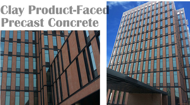
Clarify whether thin bricks will be embedded face-down in a form, installed with a proprietary liner or template, mechanically connected, bonded by another validated interface, or applied after the panel is cast. These routes have different joint formation, tolerances, testing, handling, moisture, and repair implications. This guide focuses on factory-faced precast, while final design should follow the selected precaster’s engineered and validated process.
Start with the LOPO thin facade brick overview to identify a candidate unit. Request the actual drawing, back geometry, edge condition, dimensions, tolerances, finish range, packing, and available test information. Do not specify from a colour photograph alone.
Coordinate Brick, Concrete, and Interface Inputs
| Input | Questions to resolve | Approval evidence |
|---|---|---|
| Thin brick | Actual size, thickness, warpage, back profile, absorption, edges, and finish range? | Coded drawings, samples, test data, and tolerances |
| Precast panel | Concrete mix, reinforcement, cover, panel thickness, lifting, curing, and movement? | Precaster drawings, calculations, method, and trial record |
| Facing interface | How is bond or anchorage developed, and what can interrupt it? | Representative prototype and project-specified verification |
| Form and joints | How are units located, joint width controlled, and face protected? | Formliner or template layout and approved joint sample |
| Panel interfaces | What happens at edges, returns, reveals, embeds, sealants, and repairs? | Coordinated details and full-scale mock-up zones |
Address Differential Movement and Moisture
Clay units and concrete can respond differently to moisture, temperature, curing, and time. The design should consider concrete shrinkage, thermal movement, thin-brick moisture characteristics, panel geometry, restraint, joint layout, and exposure. These factors may influence cracking, bowing, debonding, or visual alignment, but the risk cannot be resolved by a generic material claim.
Show panel joints, brick pattern discontinuities, sealant zones, drips, flashings, window interfaces, parapets, bases, and drainage paths. Decide whether joints are formed in the mould, pointed later, or completed by another controlled method. Verify compatibility between thin brick, concrete, jointing materials, sealants, cleaners, form liners, release agents, and any repair materials.
Use Representative Samples and Trials
- Appearance set: approve identified fired pieces that represent colour, texture, dimensional, edge, and permitted variation limits.
- Small interface trial: use the proposed thin brick, liner or template, concrete, release process, joint method, and curing route.
- Production-scale mock-up: include panel edges, joints, returns, openings, embeds, reinforcement constraints, lifting, cleaning, and intended repairs.
- Verification: define bond, pull-off, shear, freeze-thaw, absorption, dimensional, or other testing only as required by the project’s standard and exposure.
- Release record: link approved samples, drawings, materials, test results, comments, and responsible signatories under revision control.
A test is useful only when its specimen, conditioning, loading, failure mode, age, acceptance criterion, and relationship to production are defined. Do not copy a value or certification from an unrelated brick, concrete mix, liner, or jurisdiction.
Plan a Controlled Precast Production Sequence
One common factory approach positions thin bricks in a mould template before reinforcement and concrete placement, but the exact sequence belongs to the precaster’s approved method. The plan should cover incoming brick inspection, storage, batch mixing, template identity, face orientation, joints, release materials, reinforcement clearances, embeds, concrete placement and consolidation, curing, demoulding, lifting, cleaning, repairs, protection, and panel identification.
- Keep the approved physical range at the inspection location and define how units are mixed across panels.
- Check that mould materials and release agents do not contaminate visible faces or reduce the intended interface.
- Record panel, concrete, thin-brick, template, curing, inspection, and repair references for traceability.
- Establish hold points before casting, after demoulding, after cleaning or repair, and before dispatch.
- Protect faces, corners, anchors, and panel edges through storage, loading, transport, and erection.
Inspect Both Factory Panels and Site Interfaces
Factory acceptance should address panel identity, brick code and range, bond pattern, joint dimensions, alignment, chips, cracks, staining, repairs, panel geometry, embeds, lifting points, and specified test records. The terracotta tile inspection checklist offers a complementary arrival workflow, but precast-specific criteria must remain in the project quality plan.
Site review should check transport damage, storage, panel location, erection tolerances, supports, connections, joints, sealants, interfaces, cleaning, and repair approval. A visually acceptable brick face does not confirm the structural precast panel or its building connections; those remain under the responsible engineer and precaster.
Prepare a Complete Procurement Package
Issue thin-brick schedules, elevations, bond pattern, colour distribution, dimensions, back and edge requirements, precast details, interface concept, standards, tests, samples, mock-ups, quantities, spares, packing, programme, and destination. The terracotta facade brick catalogue overview supports shortlisting, while the LOPO factory overview helps route current sample and manufacturing questions.
Frequently Asked Questions
Can any thin facade brick be cast into precast concrete?
No. The unit geometry, back, dimensions, moisture behaviour, tolerances, interface method, concrete process, exposure, and project criteria must be checked through a coordinated trial and evidence.
Is chemical adhesive always required?
No universal interface should be assumed. Embedded, bonded, anchored, or post-applied approaches differ. The responsible team must define and validate the proposed system using representative materials.
What should a precast mock-up include?
Include representative thin bricks, concrete, liner or template, joints, edges, returns, embeds, curing, demoulding, cleaning, lifting, repair, and any project testing needed to release production.
Who approves the bond or anchorage?
The contract should assign responsibility among the precaster, structural engineer, facade consultant, supplier, and testing body. Approval should reference the selected method, specimens, criteria, and production controls.
Request Interface and Sample Review
Send the precast drawings, panel sizes, thin-brick schedule, proposed casting method, concrete and liner information, joint design, exposure, standards, testing route, mock-up scope, quantity, programme, and destination through the LOPO project enquiry page. LOPO can review current thin-brick product feasibility; the precaster and responsible engineers must validate the complete panel and building interfaces.